Environmental Sustainability
Our Environmental Control Process
For over three decades, Emerald has been the cornerstone of the Greater Toronto Area for converting Energy from Waste. As we continue to make advancements in our technology, environmental sustainability and impact is our top priority in everything that we do.
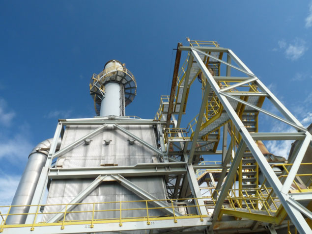
Air Pollution Control System (APC)
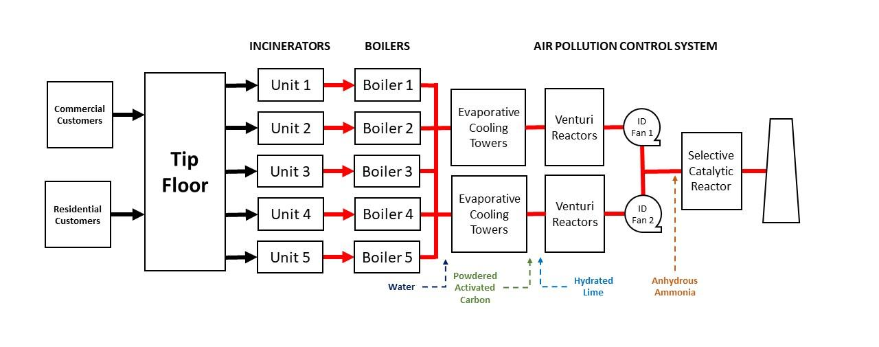
The collective flue gas emanating from the boilers undergoes consolidation in a shared duct, subsequently entering the Air Pollution Control (APC) system. This integral system serves to eliminate various contaminants present in the flue gas. Contaminants such as acid gases, mercury, heavy metals, dioxins/furans, particulates, and nitrogen oxides. Its primary objective is to ensure that emissions from the facility align with the stringent limits set forth by Ontario.
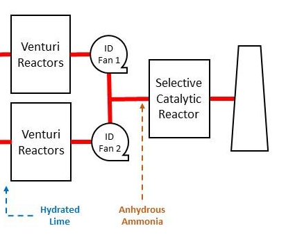
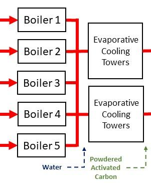
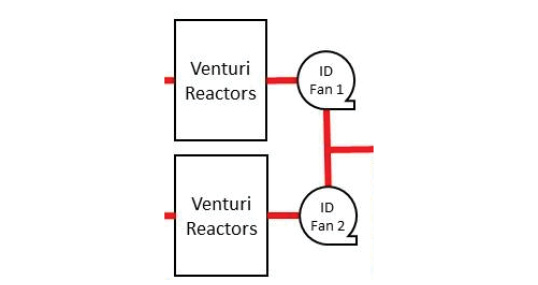
Comprising two identical treatment trains, each equipped with an evaporative cooling tower, a venturi reactor, a baghouse, and an induced draft fan, the APC system executes a comprehensive purification process. The flue gas is then recombined into a shared duct and directed towards the Selective Catalytic Reactor, culminating in its emission through the main stack. The deployment of twin APC trains serves as a strategic measure. This allows the facility to remain operational even if one train is temporarily offline for maintenance.
In essence, each treatment train is equipped with an evaporative cooling tower, a venturi reactor, a baghouse, and an induced draft fan. These contribute to the overall efficacy of the pollution control system. The duplication of these essential trains underscores the facility’s commitment to continuous operation for environmental sustainability. Therefore, ensuring operational resilience even during maintenance intervals.
Emission Monitoring
The Emerald facility operates a Continuous Emission Monitoring (CEM) system to verify that the facility operates in compliance with our operating licenses. The CEM instrumentation includes:
- Carbon monoxide and oxygen analyzers at each boiler and at the stack to monitor combustion efficiency
- Hydrogen chloride monitors located at the outlet of each Baghouse and at the stack to monitor acid gas emissions
- Opacity monitors located at the outlet of each baghouse the stack to monitor particulate/visible
- Nitrogen oxides (NOx) monitors in the flue gas duct prior to the air pollution system and at the stack to measure NOx emissions
Emerald submits reports summarizing the plant operations and emission performance to the government quarterly and annually. In addition to the real-time monitoring, Emerald commissions an independent engineer to conduct annual stack sampling. Stack sampling monitors for a variety of compounds including metals, volatile organics, semi-volatile organics, and PCB/dioxins/furans. Both the protocol for the sampling and the results are submitted to the government for review and approval regarding environmental sustainability.
Evaporative Cooling Towers
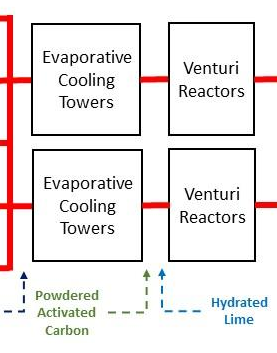
The evaporative cooling towers are cylindrical vessels through which the flue gas flows. As the gas passes up the tower, water is sprayed down into the gas stream. As the water evaporates, the flue gas is cooled and humidified to a temperature of 180°C. The cooler humidified gas facilitates the acid gas neutralization in the Venturi Reactor.
Venturi Reactors
The Venturi Reactors are cylindrical vessels that creates turbulence and contact time to enable the physical and chemical reactions. These are needed to remove contaminants from the flue gas. Hydrated lime (CaOH) acids and Powdered Activated Carbon (PAC) are added at the base of the Venturi Reactor. As the flue gas flows through the reactor, the lime reacts with the flue gas to remove acid gases (hydrochloric and sulfuric acids) and the PAC adsorbs mercury, heavy metals and dioxin and furans. The particulate-laden flue gas pass from the Venturi Reactor to the Baghouse.
Baghouse
The Baghouse filters the flue gas to remove particulate matter. The particulate removed includes dust from the combustion process, unreacted lime, and activated carbon. The Baghouse contains over 3,900 m2 of filter bags. The cleaned flue gas is drawn from the Baghouse through the Induced Draft Fans.
Induced Draft (ID) Fans
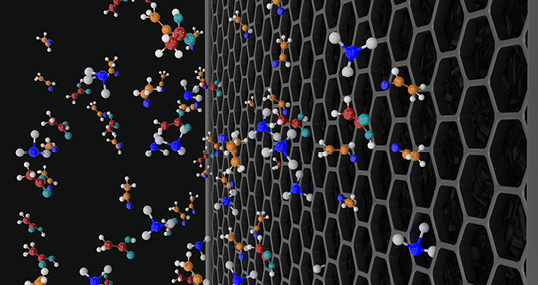
The Induced Draft (ID) fans create the draft which draws the flue gas through the gasifiers, the boilers, and the pollution treatment trains. The ID fans are powered by 400 hp (300 kW) electric motors. A single ID fan can maintain draft throughout the plant if the other is out of service for maintenance. The ID fans push the flue gas through the Selective Catalytic Reactor and out the main stack.
Selective Catalytic Reduction (SCR)
The flue gas from the ID fans is re-combined into a common duct and directed to the Selective Catalytic Reactor (SCR). The SRC system includes a duct burner, an ammonia injection system and the catalytic reduction banks. The duct burner uses natural gas to reheat the flue gas to 230°C to prepare the flue gas for nitrogen oxide reduction. Anhydrous ammonia is injected into the flue gas before it enters the SCR catalyst banks. The ammonia facilitates the nitrogen oxide reduction process. The SCR catalyst banks consist of two layers of Titanium Oxide (TiO) wire cubes. As the cleaned flue gas flows through the banks, the combination of heat, the TiO wires and ammonia reduces nitrogen oxides in the flue gas to nitrogen and water. The treated gas is emitted through the main stack. The SCR catalyst may also oxidize dioxins and furans that may be lingering in the flue gas.
